
So, I’ve been using a 3D printer to print out lots of different things for John. It’s a JG Artist-D Pro. Unfortunately, it’s required a bit of fiddling (I was hoping for fiddle free). Recently the extruder was under extruding so badly that it wasn’t even printing. So, I got a new extruder.
And these are the steps to replace the JG Artist-D extruder.
Steps:
- Change Vref from .8V to .6V.
Follow this video to open the case: https://www.youtube.com/watch?v=Kw4A6BgIjHU
Note that the case is glued down, so you have to use a good amount of force to peel it open. I bent mine a little and it took a little effort to line up the screw holes to put it back together.
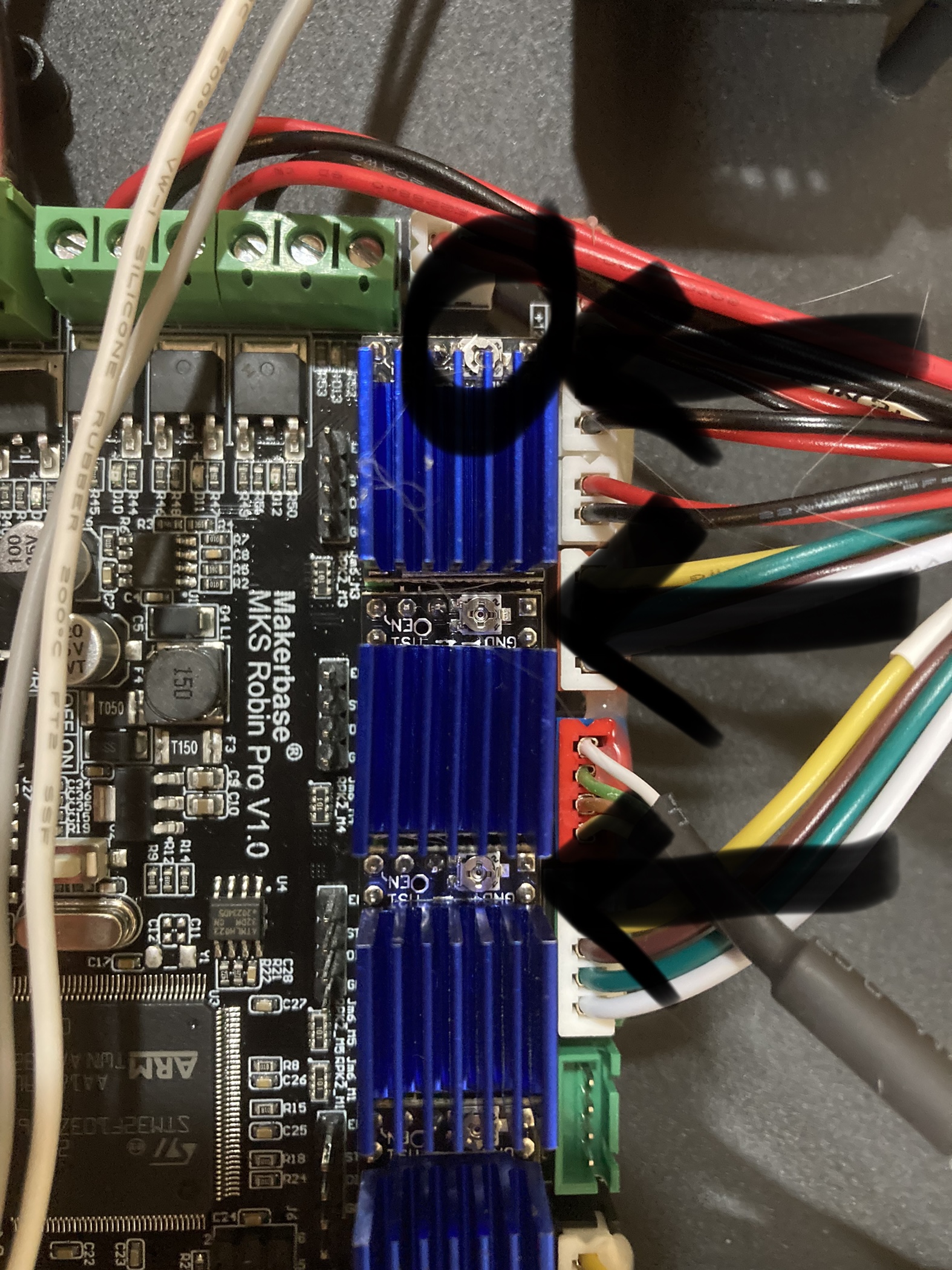
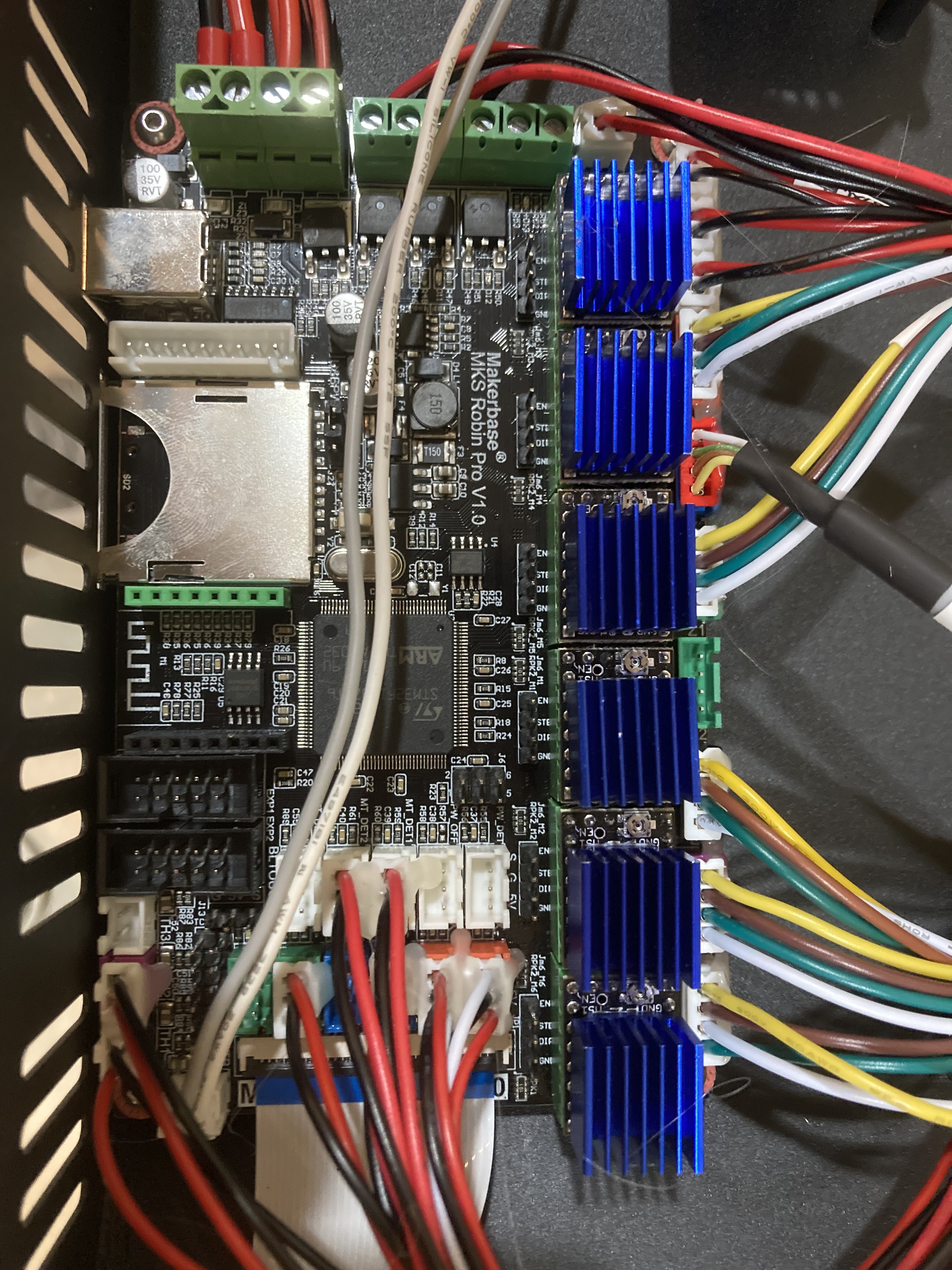
Now, locate the stepper drivers and the potentiometers (see arrows and circle).
Search for ‘Vref’ in youtube and you’ll find a bazillion videos as a reference.
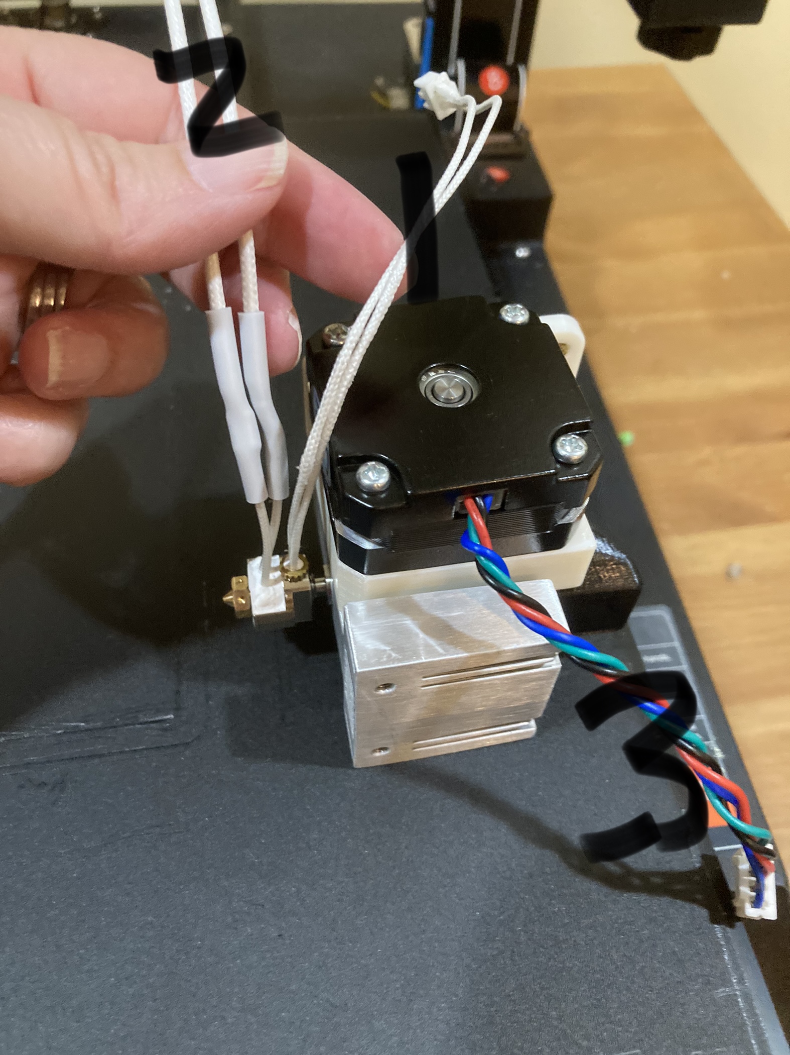
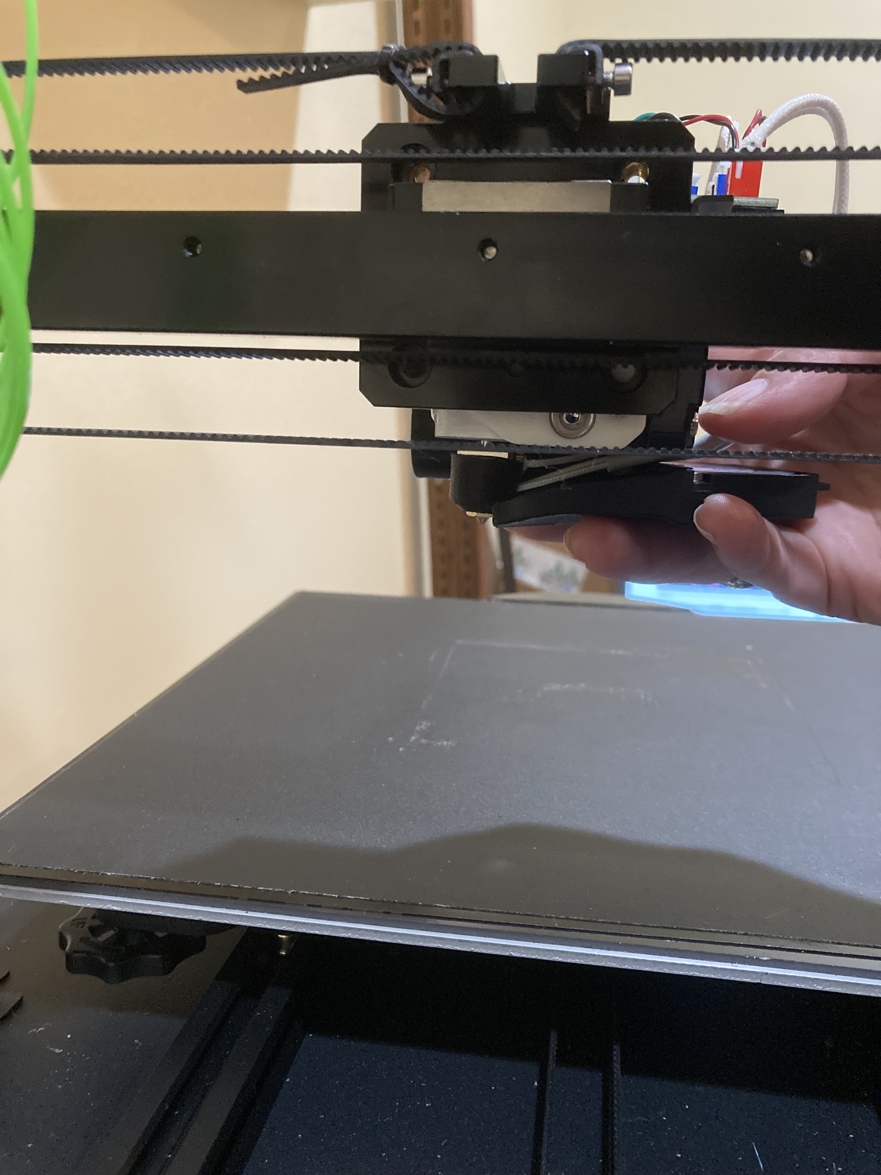
2. Take off old extruder and grab the circuit board from it.
This video is helpful just to understand how to take apart the extruder: https://www.youtube.com/watch?v=fIbvkzR5ew0&t=51s
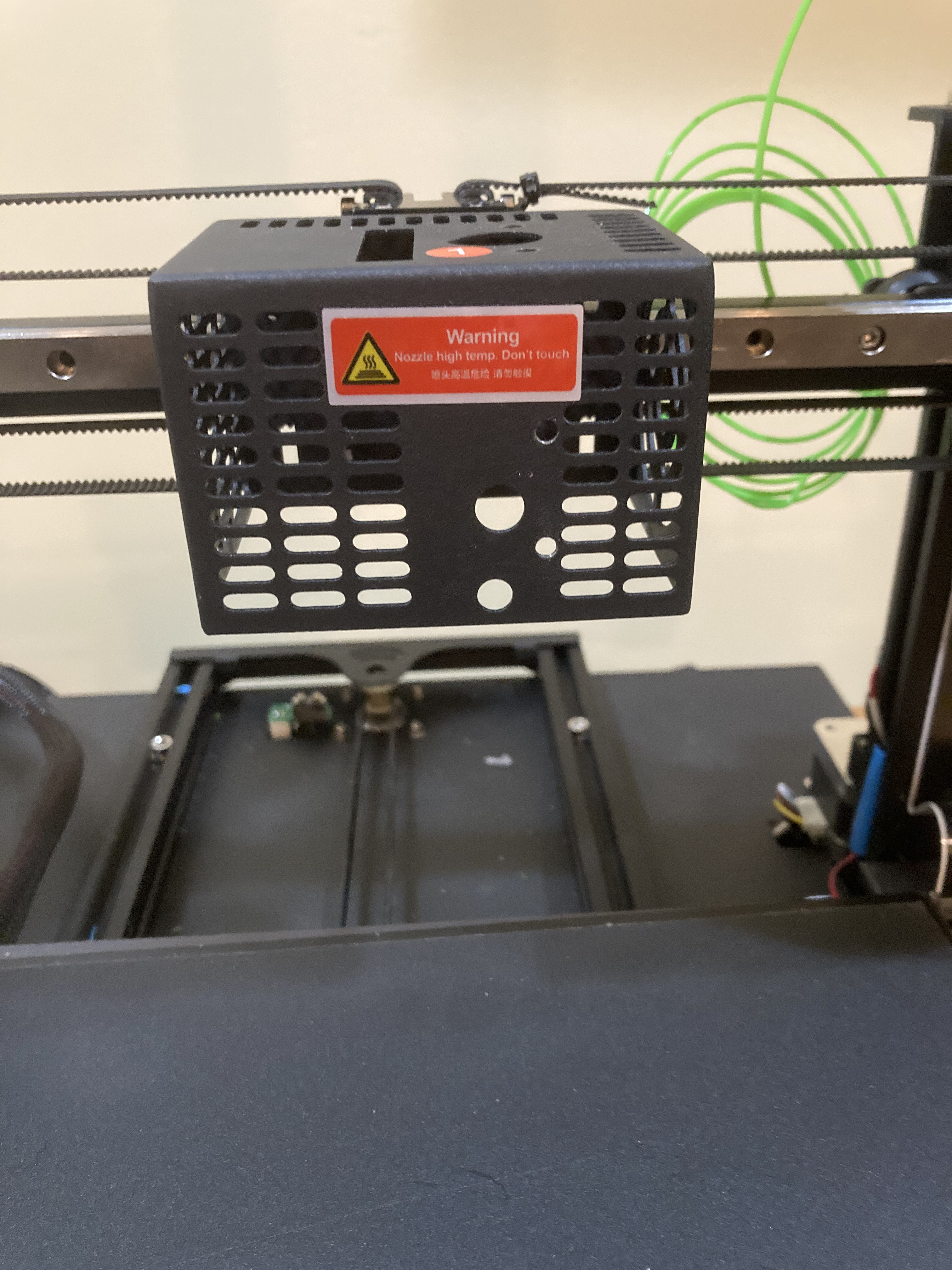
While you’re at it… take off the cage.
3. Follow the Step 1 directions on the Drop Effect Site. https://www.dropeffect.com/omniadrop-assembly

When I initially assembled it, I did it incorrectly. The nozzle in this picture is flush with the Ring Heater. This should not be the case. There should be a gap between the nozzle and the Ring Heater. Screw the Ring Heater onto the Heatbreak on more turn so that there are no more threads visible on the heatbreak. This ensures that you tighten the nozzle against the heatbreak and that there is no gap between the nozzle and heatbreak. Otherwise the hotend could leak.
4. Plug Drop Effect into old JG Extruder circuit board.

You cannot plug them in the wrong way, since there is only one way to plug them in, this is due the JST XHP connectors architecture. They will only allow you to plug them in one way.
We’ll plug in the fans in the next step.
5. Follow Step 2. of the Drop Effect Assembly

The assembly may be mirrored from what is shown on the Drop Effect website since there is a right and left extruder. Also note that the fans have a slot on one side. Make sure to orient the fan so that the slot is blowing into the air duct for both the horizontal and vertical fan. There is an arrow that points to where that slot is located.
After putting on the fans you can plug them in.
The only thing you should look out for is that the part cooling fan and the hotend cooling fan are plugged in to the right connector. The easiest way to find out is to plug them in and see which fan turns on when you start the printer.
So the cooling fan that cools the aluminium heatsink should turn on, so the vertical fan. This fan ensures that the heatsink always stays cool when the hotend is heated up.
The horizontal fan is your part cooling fan. This fan is needed to cool your prints. This fan only turns on when you print something, because in your slicer you can set how much the fan cools your print. The part cooling fan is needed you print overhang and bridges and some material need more cooling than others.TPU needs a lot of cooling while PETG and PLA need a bit of cooling, ABS and ASA should not be cooled.

6. Mount on to JG Mounting block

7. Change the PID (tuning the heater)
Follow this video to correct the settings of the PID… https://www.youtube.com/watch?v=cl-B9SrlzMY
7. Calibrate the extrusion steps
Follow this article to make sure the extruder is extruding what you think it is:
